
Die casting gives you speed, repeatability, and tight tolerances. It also punishes weak process control. Small misses show up as leaks, pits, or warped parts that break assembly lines and customer trust. This guide breaks down the most common defects you will face, why they happen, and practical ways to prevent them before they cost you rework and returns.
Many leading manufacturers, including Beyonics, refine die design, gating, venting, and real-time monitoring to reduce scrap at scale. If you need a clear, step-by-step way to stabilize quality, use the playbook below to learn How to Overcome Die Casting Defects with fast diagnostics, targeted tooling changes, and disciplined parameter control.
Porosity and Leaks
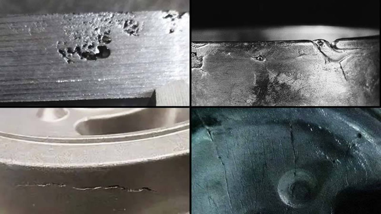
Porosity shows up as pinholes, sponge-like pockets, or hidden voids that fail pressure tests. Gas gets trapped when air cannot escape the cavity, or when alloy releases gases during solidification. Shrink porosity forms as metal contracts and lacks feed metal to fill the retreating zones. Both types weaken parts and lead to leaks after machining or impregnation.
Start with the flow path. Use a runner and gate design that fills thick sections first and keeps a consistent front. Add vacuum assist or improve venting near last-to-fill areas. Keep die lube under control because excess spray creates steam and gas. Dry the die surface before shot. Tune plunger speed profiles to create a stable shot sleeve wave and avoid air entrapment. Maintain alloy chemistry and holding furnace cleanliness to reduce hydrogen pickup and oxides that seed pores.
Tackle shrink porosity with better thermal balance. Add local cooling lines, baffles, or bubblers to pull heat out of hot spots. Use overflows and intensification pressure to push feed metal into contracting zones. Verify intensification delay and duration. Measure pressure traces, not just cavity pressure peaks. If you still find porosity after these actions, review part geometry with your customer and add fillets or local ribs to cut thick-to-thin transitions that cool unevenly.
Incomplete Fill, Cold Shuts, and Flow Lines
Short shots and cold shuts stem from a slow or broken flow front. Metal loses heat, then two fronts meet without bonding. Flow lines look cosmetic at first, yet they signal thermal or velocity problems that can grow into structural issues.
Address metal temperature first. Keep holding furnace and metal delivery temperatures within a tight range. Reduce heat loss in the ladle path. Preheat the shot sleeve and ensure a repeatable pour volume. Next, tune the second-stage plunger speed to keep the gate velocity high enough for complete and quick fill. Gate area and location matter. A small, poorly placed gate chokes flow and cools the front. Widen or reposition gates to feed thick features and far pockets.
Die temperature uniformity makes or breaks fill quality. Cold regions create early skinning that splits the front. Balance spray, switch to targeted lube patterns, and use thermal pins in stubborn cold spots. If flow lines persist, reshape internal ribs to guide the front, add overflows at weld-line locations, and polish the cavity to lower friction. Record every change and compare fill times and cavity temperatures shot to shot.
Flash, Burrs, and Mismatch
Flash appears when metal squeezes out of the parting line or around inserts. It wastes metal, forces extra deburring, and can mask a bigger problem. Mismatch is the offset between cavity halves that produces steps and thin finning along the split line.
Start by checking clamp force. Calculate the required tonnage for your projected area and gate pressure, then give yourself a margin. If flash increases during a run, the die may be opening under peak intensification. Inspect tie bars, nuts, and platens for wear. Clean and re-stone parting lines. Replace worn locks and guide pins. Even a small gap invites metal to escape.
For mismatch, inspect locating features and bushings. Verify die face flatness and parallelism on the press. Thermal growth can tilt the die if one side runs hotter. Balance cooling circuits and change lube patterns that over-cool a single corner. If flash persists despite proper tonnage and alignment, lower metal temperature slightly, reduce intensification pressure, or trim gate velocity. Make one change at a time and log results with timestamps so you can trace cause and effect.
Soldering, Sticking, and Die Erosion
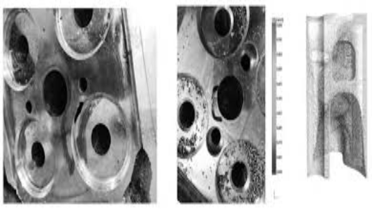
Soldering is metal bonding to the die steel. It leaves patches on the cavity and scars the part surface. Sticking slows ejection and raises cycle time. Erosion chews the die in high-velocity zones and near gates, which then feeds inclusions and surface defects back into the casting.
Tighten alloy control. High iron content in aluminum reduces soldering. Keep within the spec window for your grade. Remove contaminants and maintain holding furnace flux practice. Adjust die lube type and film thickness. Too little lube encourages adhesion. Too much lube kills flow and traps gas. Use coated core pins and inserts in hotspots. Nitriding, PVD coatings, or premium tool steels handle thermal shock better and slow wear.
Revisit gate design to cut jet velocity on sensitive features. Blend sharp turns, add radii, and move impact away from thin steel. Check ejector layout and stroke timing. Polish critical draw surfaces to a consistent finish so parts release cleanly. Keep the thermal map steady. Sticking usually increases when a region runs hot and grabs the skin. Add localized cooling, shorten spray in that area, or use pulse cooling to stabilize surface temperature.
Blisters, Warpage, and Dimensional Drift
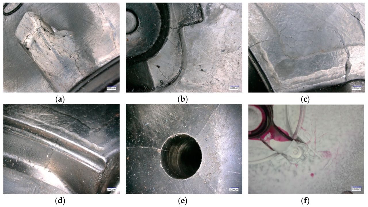
Blisters form during post-process heat exposure or paint bake. Trapped gas or residual die lube expands and lifts the skin. Warpage bends parts during ejection or cooling. Dimensional drift shows up as creeping size changes across a run or between lots.
Prevent blisters by reducing entrapped gases during fill and by drying the die face before shot. Shorten spray time and increase air blow to dry cavities. Reduce die lube volatility in paint-bake-sensitive programs. Validate bake cycles on real parts, not just coupons. If blisters appear only after machining, you may be breaking into sub-surface porosity. Re-locate features or improve feed to the area during solidification.
For warpage, look at ejection timing and mechanical balance. Parts bend when one side grips the steel or when cores pull unevenly. Re-polish draw surfaces, add ejectors near flexible ribs, and check core alignment. Thermal symmetry matters. Match cooling line flow rates, and review cycle time against actual metal temperature at open. Dimensional drift often ties to die growth and machine settings. Record metal temperature, cavity temperature, plunger position profiles, and intensification timing. Lock down recipes by part number and revise only under change control. Gauge first-off, mid-run, and last-off parts to catch trends before they reach customers.
Inclusions, Oxides, and Cosmetic Failures
Inclusions and oxides create dull patches, pits, and weak zones that break during machining. They arrive from dirty melts, turbulence, and dross carryover. Cosmetic failures can look simple, yet they often trace to upstream control issues.
Clean the melt. Skim dross, use ceramic filters where practical, and keep the holding furnace covered. Establish a calm pour practice. Align ladles to avoid splashing in the shot sleeve. Use slow first-stage plunger movement to build a smooth wave, then accelerate sharply into the second stage. A smooth transition reduces turbulence and air entrainment.
Polish cavities to the finish your customer expects. Control die lube overspray, since overspray leaves streaks and fisheyes. Vent last-to-fill areas and add micro-vents if the tool design allows it. If you paint or plate parts, run a pre-treatment audit. Residual release agents and oxides interfere with coatings. Simple checks like contact-angle tests and dyne pens can predict adhesion problems before a full paint trial.
A Practical Troubleshooting Playbook
Good casting lines run on data, not guesses. Build a short list of process signals that predict defects. Track metal temperature at ladle and gate, cavity temperature by region, plunger position curves, fill time, intensification delay and peak, spray time, and airflow during dry. Save the trace for every shot in a sample window each shift, then compare against a golden run.
Standardize experiments. Change one factor at a time. Record the exact value, time, part ID, and the measured result. Use X-bar and range charts on porosity counts, pressure test leaks, and critical dimensions. If a trend appears, lock the winning settings and update the setup sheet, tool maintenance log, and operator checklist. Train crews to spot early signals, like a rising fill time or a new lube sheen on a surface.
Hold tooling reviews on a fixed cadence. Inspect vents, overflows, gates, ejectors, and coatings. Replace tired pins before they score parts. Calibrate temperature and pressure sensors so your reports reflect reality. Share the same dashboard with quality, maintenance, and production. When everyone sees the same facts, root-cause work moves faster and scrap falls.
A stable die casting process comes from disciplined control of heat, flow, pressure, and time. Each defect points to one or more of these factors. When you map symptoms to likely causes, verify with data, and act with a clear test plan, quality improves and cost per good part drops. Keep the loop tight. Measure, adjust, and document. Your parts, your customers, and your margins will show the result.